Soil Resistivity Information and Field Testing
The evaluation of grounding systems, cathodic protection systems, and several other infrastructure studies require knowledge of the electrical characteristics of the soil. Typically, engineers are concerned with the soil’s allowance of electrical current, characterized as the soil resistivity with an SI unit of Ω-m.
Free Intro to Grounding Analysis Book
 Learn more about the concepts in this article and related content in the Introduction to Grounding Analysis Book download for free! This free book serves those in the power industry responsible for analyzing the performance of a grounding (earthing) system, specifically with regard to IEEE Std 80, Guide for Safety in AC Substation Grounding. It is a comprehensive and valuable resource that shows the need for and how to do grounding analysis.

At a fundamental level, the conduction of electricity in the earth is primarily driven by two types of current contribution:
- Ionic (or electrolytic) contribution: movement of free ions in the material
- Electronic contribution: movement of free electrons in the material
Usually, electrolytic conduction is the predominant factor for electric current to flow in soil, and is affected by the soil’s moisture, temperature, and chemical content. The factors that promote or inhibit electrolytic solutions in the soil decrease or increase the soils resistivity, respectively. Assessments based on soil classification from literature yield only a rough approximation of the resistivity for a particular site. The great variation, even for soils that are similar in appearance, is shown by the table below:
| Type of Soil | Resistivity Range (Ω-m) |
|---|---|
| Clay | 15-150 |
| Loam | 15-100 |
| Sandy Clay | 50-300 |
| Sand | 200-3000 |
| Gravel and Sand | 500-5000 |
| Solid Rock | 10000+ |
Actual soil resistivity measurements are required and should be performed at several locations within the site, or as close as possible. Sites where the soil may be characterized by uniform resistivity throughout the entire area and up to a considerable depth are seldom found. Often, vertical stratification of the soil yields several layers of different resistivity. Lateral changes also occur, but are usually more gradual compared to the vertical changes. Studies show the resistivity of soil layers tens or hundreds of feet deep affect a project’s outcome, such as the ground potential rise increasing for a grounding study. We cannot overstate the importance of accurate measurements to the breadth and depth necessary for each specific project.
Four Pin Resistivity
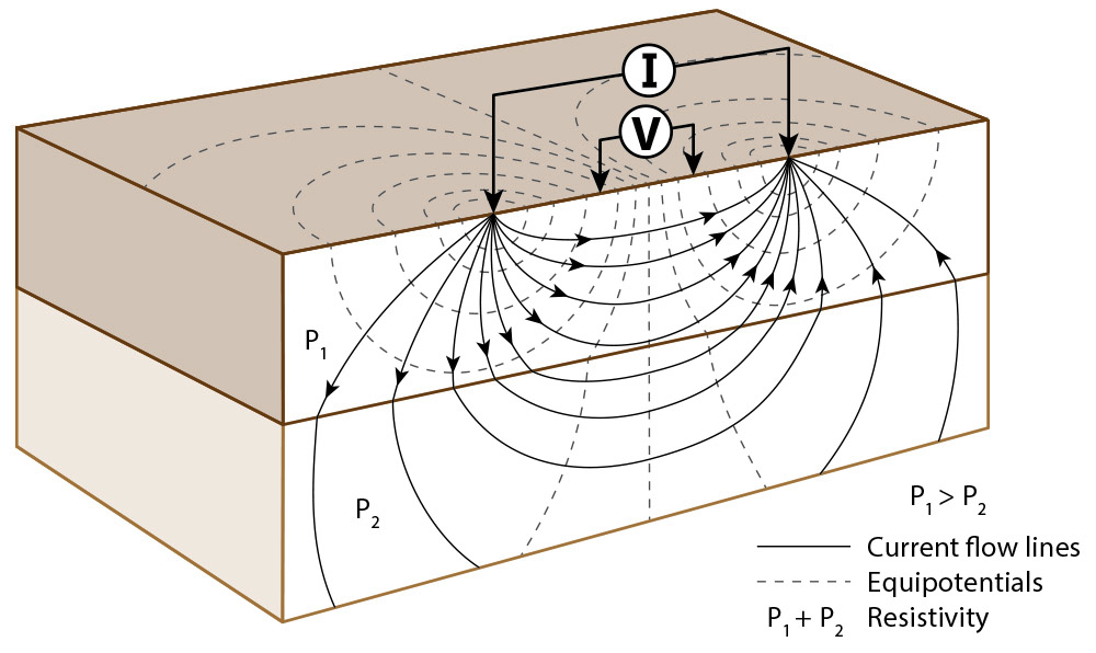
There are many methods to acquire soil resistivity measurements, but the most common are the Wenner and Schlumberger methods, also called the four-pin methods. Regardless of the method, the general concept can be described as injecting a known current into the soil and measuring a voltage. The following figure represents the current flow and the equipotential lines produced by a current that is injected through the ground with two different soil layers.
Soil resistivity measurement
Wenner Method
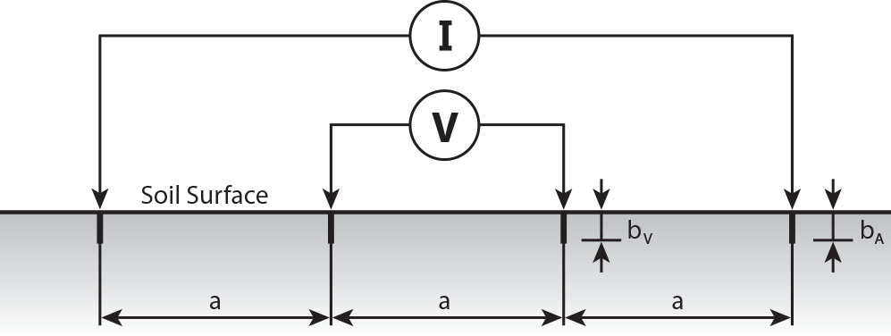
The Wenner alpha four-pin method is the most commonly used technique for soil resistivity measurements. It is performed by placing four pins at equal distance, injecting a known current on the outermost electrodes and recording the voltage between the interior electrodes. The following figure illustrates the Wenner alpha four-pin method.
Wenner alpha four-pin method
If the depth of the probe, b << a, as is the case of electrodes penetrating the ground only for a short distance (as usually happens), the apparent resistivity can be calculated as follows:
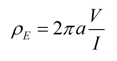
Using the Wenner alpha method, the electrode spacing is increased along a path to measure greater depths of soil. This is possible because, as the electrodes spacing is increased, the test source current penetrates greater areas, in both vertical and horizontal directions, regardless of how much the current path is distorted due to the varying soil conditions. Smaller electrode spacing measurements, shallower measurements, are important to characterize the soil with which the grounding system will be in contact. Longer electrode spacing, deeper measurements, are typically taken such that the maximum spacing between pins is equivalent to the maximum dimension of the grounding system to be evaluated. If the resistivity varies appreciably with depth, it is often desirable to increase the range of electrodes spacing to assess the resistivity.
Schlumberger Method
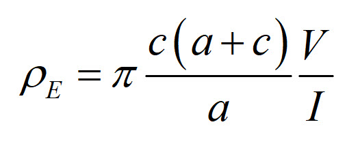
In the Schlumberger method, the distance between the voltage electrodes “a” and the distances from a voltage electrode and a current electrode “c” are different (see figure).
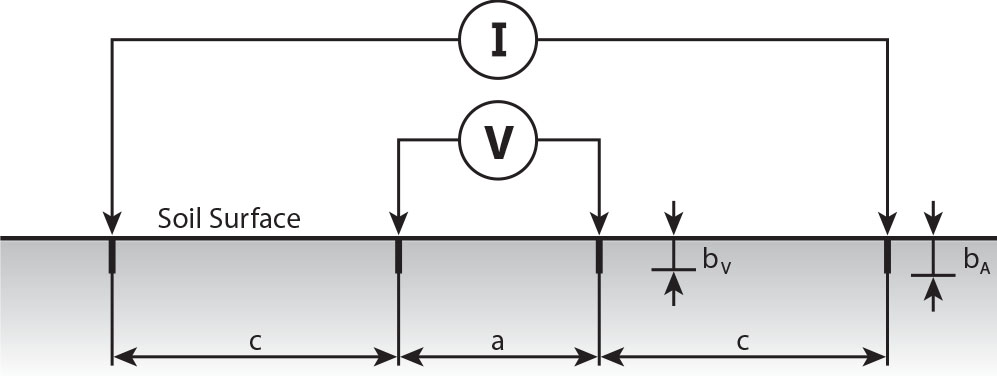
Schlumberger four-pin method
If b << a and b << c (as usually happens), the apparent resistivity can be calculated as follows:
The configurations with a > c is known as the “Schlumberger – Palmer method” while the configuration with a < c is known as the “Schlumberger method.” Compared to the Wenner method, the Schlumberger method is less laborious because it does not require the interior voltage electrodes to be reinstalled for each measurement. The Schlumberger method is also advantageous in that shorter measurement cables, smaller free space, and less time are needed to conduct the testing to acquire resistivity measurement of equivalent depth to the Wenner method.
Compared to the Wenner method on equal terms, using the Schlumberger method with c > a requires more sensitive instruments because the measured resistance is lower, while with c < a the measurement may be easier with a greater measured resistance.
Measurements Challenges
Regardless of the measurement procedure, there are challenges for getting accurate measurements for a site. Typical issues include:
- Electrode/probe continuity
- Buried metallic systems interfering with native soil measurements
- Inductive coupling of testing leads or external sources
- Insufficient power and/or sensitivity of the measurement device
Simple techniques including additional probes, saltwater, or perpendicular measurements can overcome some of the issues above. Symptoms of these issues can be recognized by experienced technicians and engineers performing the test to allow for testing plan modifications.
Field Testing
Prior to the testing, personnel need to outline a test plan to develop goals and mitigate the challenges noted above. As an example, a new site highlighted in yellow below will have a grounding system with a maximum dimension of 200 feet. Using the Wenner Method to acquire soil resistivity measurements, test traverses shown in red provide shallower resistivity at the site, with measurements farther away to access deeper soil resistivity on the order of 200 feet, for a total traverse length of 600 feet.
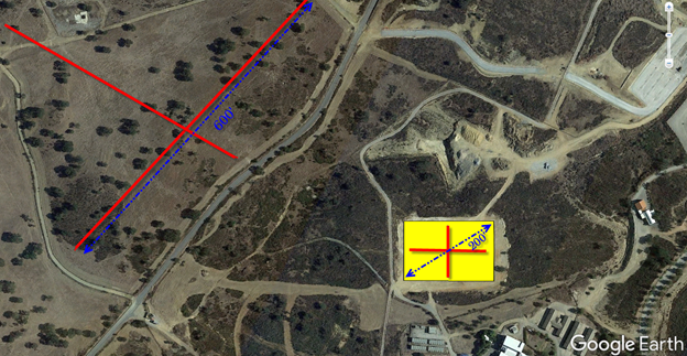
Note that each location includes two perpendicular traverse to help identify interference in measurements.
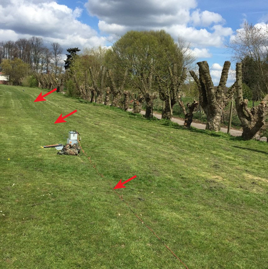
Often two or more measurements can be performed at a probe spacing that is shallower than the grid depth, such as 9 and 18 inch electrode spacing, which progress to larger electrode spacing to match or exceed the dimension of the grounding system. The image below, courtesy of GreyMatterGlobal, shows this test in the field.
Adequate planning and preparation provide better soil resistivity data to more accurately analyze a grounding system.
Additional Considerations with Soil Data
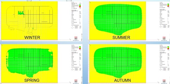
Performing soil resistivity measurements, like the approaches described above, are pertinent to accurately evaluate various types of studies; however, measurements will provide the electrical characteristic of the soil at a specific time. Factors like temperature, moisture, and chemical content primarily affect shallower soil layers, but can significantly impact an analysis. Chemical content is typically influenced by human interaction, while moisture can vary from day to day due to precipitation. Fortunately, temperature is generally predictable allowing for calculation methods to determine the change in soil resistivity between seasons. In regions where the soil may freeze, ion movement becomes limited, often dramatically increasing resistivity. The Seasonal Analysis tool in XGSLab shows how temperature can influence a grounding system from compliant touch and step voltages in the summer, to hazardous conditions just a few month later (note areas in yellow that indicate non-compliance for touch voltages).
It is important for engineers to understand the accuracy and limitations of the measurements they use for their studies as it has a significant impact on their designs.
XGSLab™ Grounding Solution
XGSLab is one of the most powerful software for electromagnetic simulation for power, grounding and lightning protection systems and the only software on the market that takes into account International (IEC/TS 60479-1:2005), European (EN 50522:2010) and American (IEEE Std 80-2000 and IEEE Std 80-2013) Standards in grounding system analysis.