AC Interference in Shared Corridors
The process for routing transmission lines can take significant time and effort before engineering design and studies truly begin. An existing right of way with pipelines, railroads, or other facilities greatly simplifies this process, but requires compatibility studies.
The term AC interference in the power industry refers to the effects power systems can have on adjacent facilities and structures. An incredible level of engineering design and analysis is incorporated into many aspects of our modern life, and is apparent through the multi-industry collaboration that AC interference studies require. This article describes the common recipients of AC interference, explains the physics of AC interference, and gives an outline for the process to evaluate these complex interactions.
Recipients of AC Interference
Power systems produce electromagnetic fields that can energize nearby metallic objects that can be of sufficient magnitude to be a shock hazard for personnel and the public. The fields may be significant to damage the metallic recipient or its supporting components. Often a transmission line sharing or crossing an existing right of way prompts an evaluation of AC interference. Common recipients of AC interference include:
- Pipelines
- Railroads
- Communication cables
- Metallic fencing
- Buildings
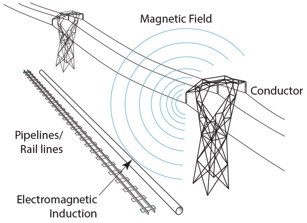
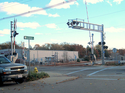
The image above illustrates a potential shared right of way with a transmission line, pipeline, and railroad. Each requires long linear paths and it is not uncommon for these industries to use the same right of way.
Physics of AC Interference
There are three coupling mechanisms that are evaluated as part of an AC interference study:
- Inductive Coupling
- Capacitive Coupling
- Conductive Coupling
When evaluating AC interference, all these coupling modes may simultaneously affect the voltage and current on the recipient.
Inductive Coupling
Alternating current in power systems produces a magnetic field. This magnetic field induces an opposing voltage and current on parallel metallic objects, as shown in the image below.
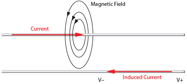
Three-phase balanced operation produces equal magnetic fields around the phase conductors, but the field strengths vary with the separation from each phase conductor to the recipient. The inductive coupling generally has a linear relationship with the power system current and exposure length.
Capacitive Coupling
The electric field from power systems capacitively couples with a recipient, dependent on the field strength and exposure area. This coupling can be significant for some objects that are insulated from the ground, such as vehicles, so that an individual who is in contact with the energized recipient is unable to release due to uncontrolled muscle contraction. Capacitive coupling is insignificant for buried pipelines or other objects below grade as the electric field’s strength is weakened by the ground and grounded objects.
Conductive Coupling
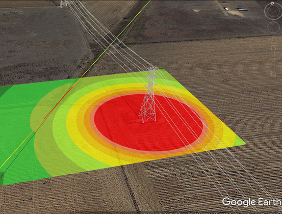
In fault conditions, current may flow through the soil or another medium. This results in direct conduction from the power system to the recipient. The image below is exported from XGSLab and illustrates a ground potential rise around a faulted transmission structure transferring to an adjacent pipeline.
Pipeline Considerations
There are over a million miles of pipeline in North America, which provides many sites with a potential issue with AC interference. Along those pipelines there are several locations that personnel regularly interact, and those locations could be susceptible to touch voltage hazards. These can be pump stations, test sites, valves, or other appurtenances that require evaluation to confirm voltages do not exceed acceptable limits either during steady state operation or faulted conditions of the power system. It is also possible that buried pipeline sections will need to be accessed for repairs, presenting a new location for touch voltages to occur. Typical steady state touch voltage limits aim to reduce touch voltages below 15 V – 50 V. During the short duration of a fault, higher touch voltage limits are typically calculated using the methods from IEEE Std 80.
In addition to personnel hazards, the pipeline itself may have reduced lifespan or immediate damage. Pipelines often have protective coating to reduce corrosion, possibly using impressed current systems to provide greater resistance to corrosion. Transmission lines inducing voltages on pipelines may hinder these measures through AC corrosion. Defects in the pipeline coating may allow AC corrosion when current density exceeds 20 A/m2 – 30 A/m2. During fault conditions, there may be sufficient voltage in the soil to puncture the pipeline’s coating and damage other components like pipe flanges.
Railroad Considerations
Like pipelines, railroads may have sufficient voltage on the tracks to be a hazard for the public and personnel. In steady state operation of the power system, a typical touch voltage limit of 50 V should be achieved at all points of the track and pertinent track circuitry. It is important to note many railroads use insulating joints to separate track circuits that can be locations of increased track voltage. These insulated joints may have a magnitude of 25 V in opposing polarity resulting in a total of 50 V across the joint. During the short duration of a power system fault higher voltage limits are typically used, based off the calculation methods of IEEE Std 80, or referencing the 430 V or 650 V limits from AREMA.
The standard width of railroad tracks is 4 feet 8.5 inches, which provides some asymmetrical effects from AC interference. Track signaling used to determine train location and speed and that operate grade crossings may mis operate where a 5-volt difference in the track exceeds the filtering capabilities of some track equipment. If an insulating joint is failing, this track imbalance can become significant. During a fault, higher induced and conducted voltages can exceed the limits of track arrestors and damage track equipment.
Evaluating AC Interference
Evaluating AC interference can be technically complex and logistically challenging requiring collaboration of several industries that do not typically interact. Data requirements of the power system include:
- Plan and Profile
- Phasing/Attachment Geometry
- Conductor Information
- Shield/OPGW
- Structure Grounding
- Load Current
- Fault Current
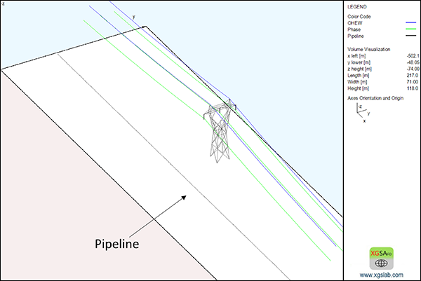
Similar detailed information is required for the recipient under evaluation of the AC interference. These systems are then combined in an electromagnetic field calculation program, like XGSLab’s XGSA_FD that can incorporate all the electrical properties in the model and evaluate the effects of inductive, capacitive, and conductive coupling simultaneously. The image below shows a pipeline running parallel to a transmission line in XGSA_FD.
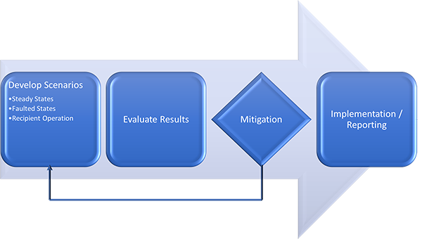
Once all the model is developed, there are several scenarios to evaluate from various steady state load conditions to multiple fault locations. This can be a highly iterative process if mitigation is required to meet the analysis objectives.
Capturing the pertinent aspects of an AC interference analysis is important for providing an engineering solution that accurately resolves the problem. Tools like XGSLab with the Scheduler enable multiple scenarios to be ran, but each scenario should be reviewed by the engineer performing the analysis. For more information you can view our AC Interference webinar, which provides a case study for mitigating AC interference on a parallel pipeline.
XGSLab™ Grounding Solution
XGSLab is one of the most powerful software for electromagnetic simulation for power, grounding and lightning protection systems and the only software on the market that takes into account International (IEC/TS 60479-1:2005), European (EN 50522:2010) and American (IEEE Std 80-2000 and IEEE Std 80-2013) Standards in grounding system analysis.