Avoiding the “Ball of Spaghetti” One-line
We often see a wide variety of sophistication when users submit their one-lines to us for assistance in modeling their electrical distribution systems. Fortunately, EasyPower has some very useful layout capabilities you can use to ensure a better layout of the one-line model. All it takes is a small amount of planning and a handful of very useful tools. The following is a brief list of suggestions that can bring order to your final drawing and avoid the semblance of a bowl of pasta.
Start Small
Often, new users of EasyPower are under the gun to finish an arc flash study before they even start drawing. This pressure may encourage them to try to complete the entire system in a one-line model as a first step. However, it is better to start with a small system and work your way up.
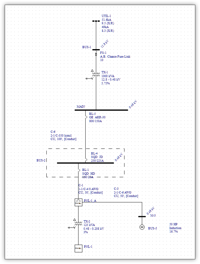
- First, draw a simplified system, connecting one energy source (such as a utility, generator, or battery) and one or two system loads for which the intent is to produce an arc flash label with correct energy predictions.
- Ensure this simplified model contains an example of each type of disconnect or interconnects (switchgear, MCC, or panel) and protective device (fuse, relay, LVPCB, and MCCB) that you have in your actual system.
- Now, attempt to analyze this simplified model—not for incident energy results, but to check the mechanics of the EasyPower program. Are you missing any required data? Can the model produce the results you need for equipment duty, proper coordination, and arc flash boundaries?
Even after you have mastered the mechanics of using EasyPower, build your one-line in sections and verify satisfactory results along the way.
Collect the Right Data
The most common cause of wasted time (which drives up the overall cost of the study) is not collecting the necessary information during data collection, thus requiring a second or third trip to the site of the equipment to complete the study.
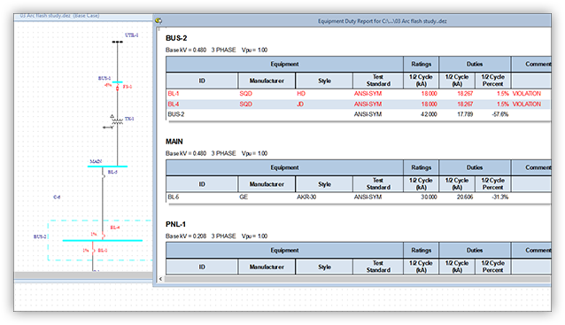
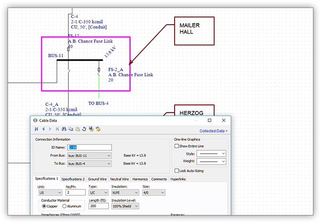
- Equipment duty is a calculation that EasyPower performs if the Bus Rating has been correctly entered as part of the model development. This is an area often missed by first-time data collectors. The lack of data may not be apparent until you attempt to generate a short circuit report. (Image Two A) (Image Two B)
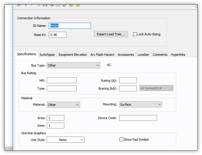
- In EasyPower, the bus Type determines the default air gap dimension used in the arc flash incident energy calculations. “Other” is probably not the selection you want for your main bus (see Image Two).
Plan Your Final Layout in Advance
EasyPower (and its scaled-down version, OneLine Designer) include the powerful Database Edit feature that provides CAD utilities that greatly amplify the usability of your final one-line diagram. With some forethought, your model can be intuitive and easier to use. Keep in mind that the entire system must be on the one-line.
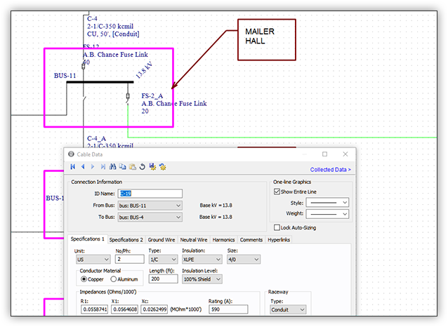
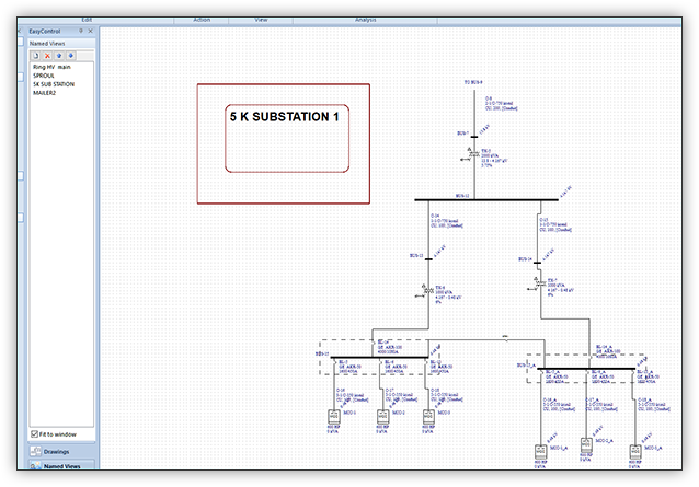
- For large systems, it makes sense to plan the layout to include several separate “panes” that include logical equipment groupings. Examples might be all the equipment on a floor, or all the equipment attached to a substation. This is especially useful in a campus setting, where each building can be a separate pane on the one-line.
- As you place equipment on the one-line, you can put them in the location for the designated pane. Then the connecting cables can be “stubbed off” using the Show Entire Line setting on each cable. This ensures the overall one-line remains clean and easy to follow.
- The use of color can be another way to clarify information or grouping of equipment. The designation of redundant or backup networks can be color coded for easy identification.
Use Drawings
Using the EasyControl features, you can create separate Drawings that include specific elements in the system such as MCCs, panels, or large loads. After you name the drawing, you can include additional elements such as panel or MCC schedules for added emphasis on pertinent system information.
- Use informational annotations such as text and boxes to provide more clarity.
- Set sheet sizes and use custom title blocks for a consistent presentation format.
These separate drawing sheets are updated as changes are made to the main drawing.
Use Named Views
Also within the EasyControl feature is a Named View function. For each of the “panes” of logical equipment groupings you created earlier, you can create a named view. This reduces the need to pan and scroll around the one-line to find equipment—just select the named view and your one-line is immediately focused on the equipment within that view. This gives you instant access to the different equipment groupings from any location of the one line.
Use Find-Select
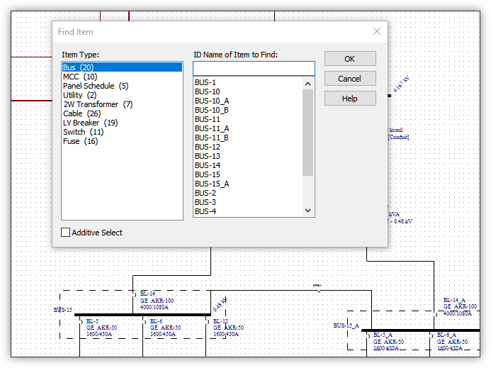
Even with unique equipment names assigned, it can be difficult to find a single item on a large one-line. The most efficient method for locating individual system elements can be achieved using the Find tool in the Database Edit focus.
The Find-Select button is available from any focus on the one-line. The dialog box displays a list of each equipment Type, such as bus or panel. After you select a type, the program displays all the system elements of that type. You can type the ID name or scroll the list to select the item you are looking for. That portion of the one-line diagram is brought to the center of the screen view that you are using.
Conclusion
Starting small to test the system, ensuring you’ve collected the necessary data, planning your layout in advance, and learning to use the drawings, named views, and find-select functions significantly improves your productivity and helps you and your clients better understand the information contained in the system model.