Cathodic Protection
Corrosion of buried or submerged metals is the result of an electrochemical reaction. An electrochemical reaction is a chemical reaction accompanied by a flow of electrical current. Fortunately for many important pipelines, towers, and other structures, corrosion of buried and submerged metals can be controlled and limited in many ways.
Cathodic protection is only one of many methods of corrosion control and should be considered in conjunction with other forms of corrosion control, such as the application of protective coating. The adoption of cathodic protection is partly due to the fact that methods of corrosion control can be applied to existing structures. Even structures already experiencing corrosion can have cathodic protection added to prevent the corrosion damage from increasing, but of course this cannot restore the material lost due to corrosion.
Cathodic protection uses a flow of direct current to interfere with the activity of the electrochemical cells responsible for corrosion. Corrosion is prevented by coupling the metal being protected with a more active metal when both are immersed in an electrolyte and connected with an external path. In this case, the entire surface of the metal being protected becomes a cathode, thus the term “cathodic protection.”
The current flow can be provided by a source commonly called anode (or more precisely anodic groundbed or simply anodic bed). Anodes made from active metal are commonly called “sacrificial,” as the anode material is sacrificed to protect the cathode structure. Anodes made from inert metal can be implemented with impressed current, but an external energy source is used to impress this current onto the structure under protection. Sacrificial anodes are often used to protect buried structures, pipelines, or structures submerged in the sea. The image below provides an example of an impressed current cathodic protection (ICCP) system.
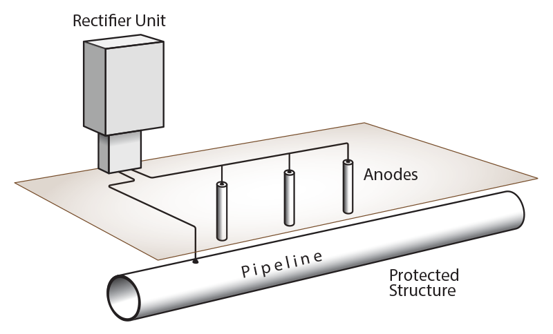
Figure 1: Impressed current cathodic protection (ICCP) system
In general sites involving large pipeline networks, the voltages drop along pipes due to the resistivity of the metal is not negligible and can affect the cathodic protections evaluations. Additionally, metallic objects located in proximity to the protected structure can change how the ICCP operates and result in some corrosion onto the collocated structures.
Impressed Current Cathodic Protection Example
In the following example, a study is performed to size a cathodic protection system with an impressed current on a buried steel pipeline. The main goal is to calculate the number and the performance of the sources of direct current required for the cathodic protection system to be effective. As these systems are often collocated with other objects, this example considers a foreign pipeline. XGSLab’s GSA_FD is used for the example.
The infinite length condition of the foreign pipeline has been simulated at both ends with a transverse impedance corresponding to the pipelines’ impedance to avoid end effects in the analysis.
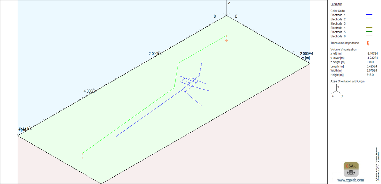
Figure 2: Layout of the pipeline to be protected (blue) and of the foreign pipeline (green)
Initial condition states than the pipeline potential is zero volts everywhere and thus the whole pipeline is subject to electrochemical corrosion. To reduce corrosion, let’s suppose the criterion for cathodic protection in the specific situation is:
-600 mV < V < -300 mV
The protection system can be designed in many ways, but the engineer’s goals are usually the evaluation of a sufficient number of cathodic protection plants and the position of the anodic beds. Anodic beds should be placed to ensure a uniform distribution of the protection current. Engineers must also consider the placement of anodic beds taking into account the availability of a power supply for the cathodic protection stations.
For this example, the distance between anodic beds and pipeline is about 100 m as an efficient compromise of costs and effectiveness. The anodic beds will be of a deepwell type instead of horizontally placed. Each anodic well will include 10 anodes, shown below. The anodes will comprise MMO/Ti (Mixed Metal Oxide coated on Titanium) tubular bar with length of 1 m and outer diameter of 25 mm.
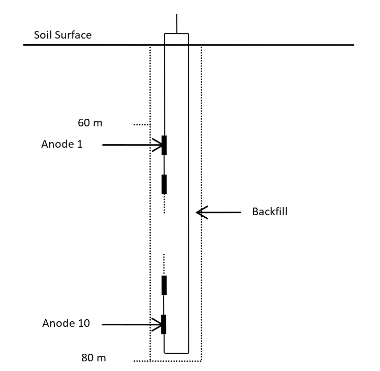
Figure 3: Anodic bed
Anodes will be uniformly distributed in the depth range between 60 and 80 m. The anodes are connected together and to the soil surface with a conductor loop to ensure the correct system operation even in case of an interruption of a cable. Each anodic bed will be backfilled with a low resistivity material with the purpose of decreasing the effective resistance between the anodes and the earth. A low resistance between the anodes and the earth makes for more effective cathodic protection and reduces operating costs. In the example case, calcinated petroleum coke (as usual with MMO/Ti anodes) has been considered.
After some preliminary designs, the following final solution finds that the system can be protected using 3 cathodic protection plants with 4 A current in the locations indicates in the figure below.
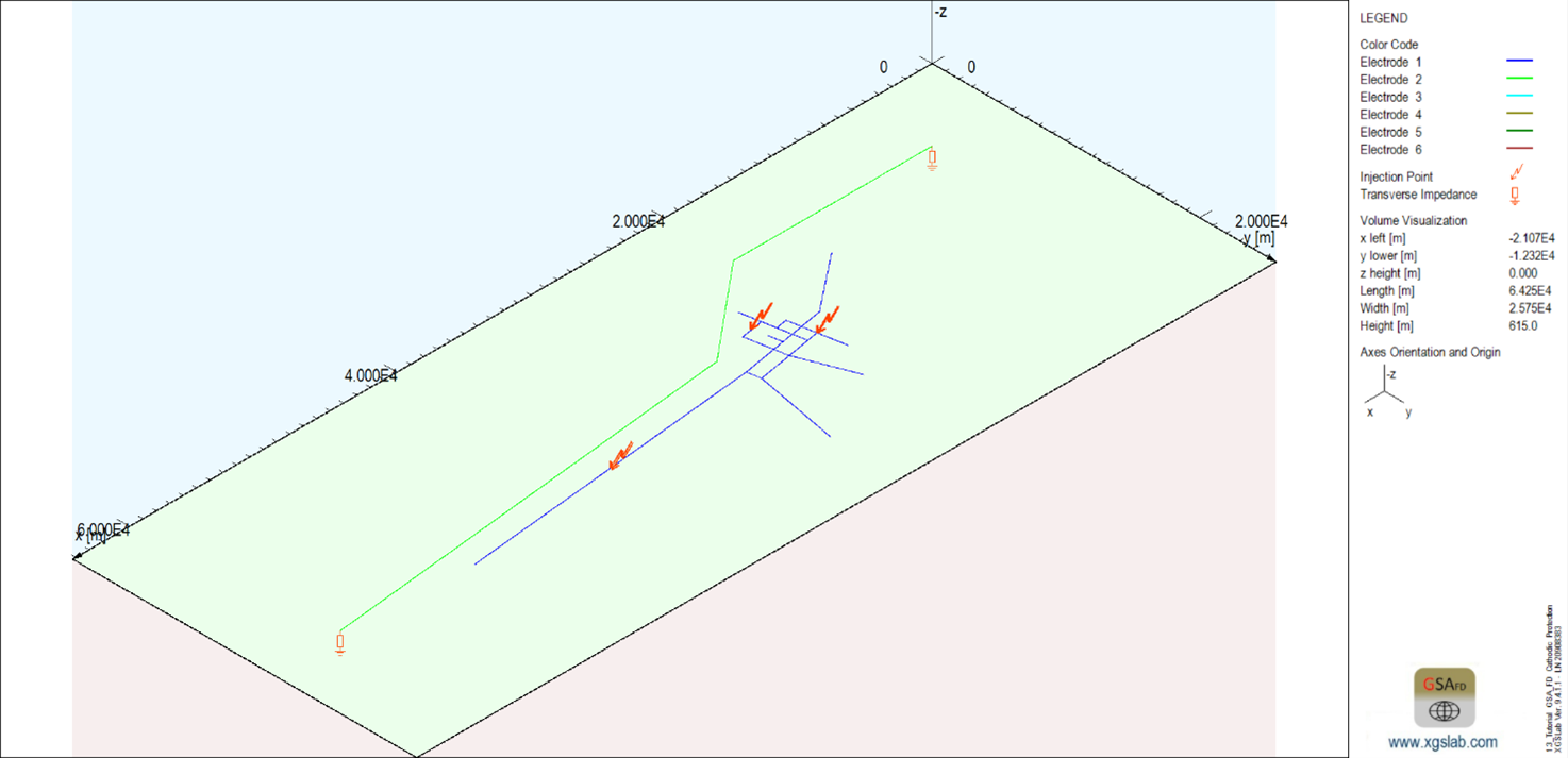
Figure 4: General layout including anodic beds
The figure shows the system model with a blue color gradient applied to the pipeline to indicate the voltage distribution level. This shows a relatively equal distribution of voltage potential on the protected pipelines.
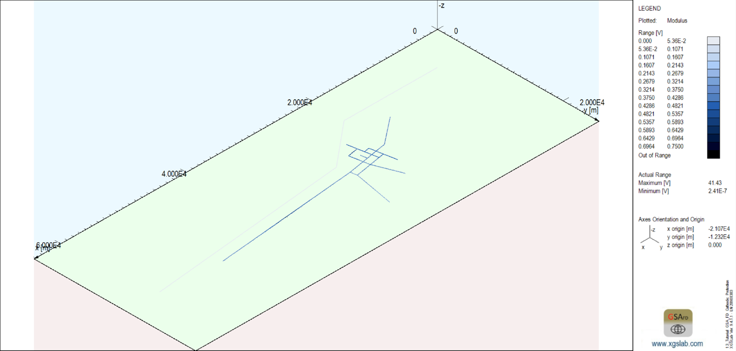
Figure 5: Potential distribution on pipeline to be protected
The voltage distribution of the protected pipelines is shown below in green. This more clearly illustrates that the potential is in the target range of -600 mV and -300 mV. As a result, protection conditions are fulfilled everywhere.
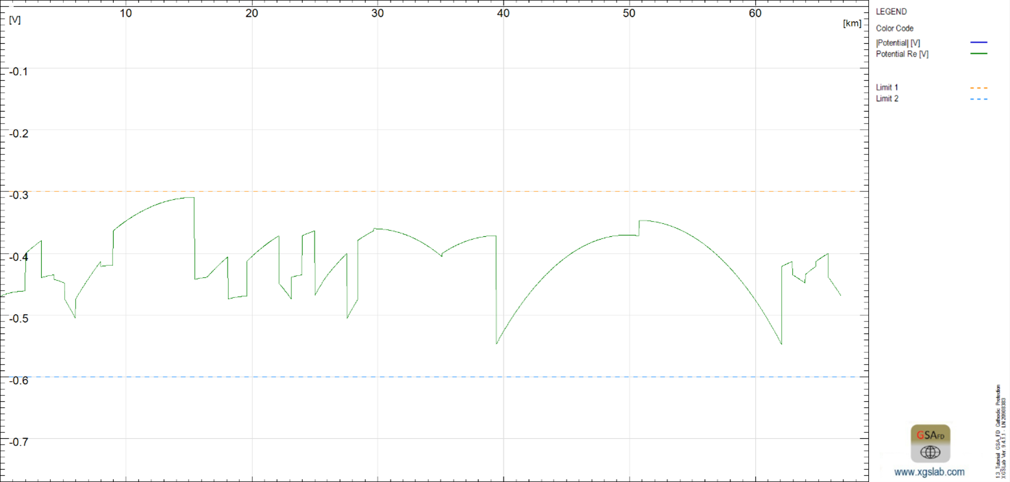
Figure 6: Potential distribution on the pipeline to be protected
Additionally, the earth surface potential from the ICCP as indicated in the figure below shows non-hazardous voltage levels for personnel, as is typical of ICCP. Note also that some sections of the neighboring pipeline pass through soil regions that are affected by the ICCP, thus affecting the neighboring pipeline’s corrosion protection.
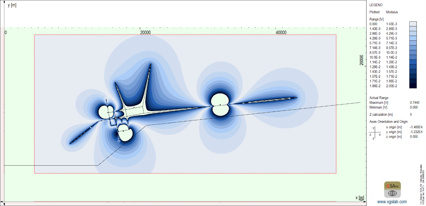
Figure 7: Earth surface potential distribution
XGSLab™ Grounding Solution
XGSLab is one of the most powerful software for electromagnetic simulation for power, grounding and lightning protection systems and the only software on the market that takes into account International (IEC/TS 60479-1:2005), European (EN 50522:2010) and American (IEEE Std 80-2000 and IEEE Std 80-2013) Standards in grounding system analysis.