Understanding NESC 5 mA Let-Go Shock Hazard
An advantage of using the alternating current in power systems around the world is the ability to transform voltage to transfer more energy farther with greater efficiency. The bulk electric grid consists of multiple high voltage transmission lines that provide power to substations where the voltages are reduced to distribution levels through a transformer. The electromagnetic fields (EMF) that allow the transformers to bring high voltage to distributions voltage levels are present throughout the whole of the line and may produce hazards on nearby recipient metallic objects.
The NESC and other standards provides guidance on the minimum ground clearance of transmission lines to prevent direct contact and reduce, though not eliminate, EMF related hazards. As each phase has 120-degree separation, the fields will cancel with closer proximity, thus medium and sub-transmission voltages level are not typically scrutinized for EMF hazards. As voltages increase, there is a greater phase separation allowing a single phase to primarily interact with recipient objects and may require an engineering study. The NESC specifically guides high voltage transmission lines exceeding 98 kV to either increase clearance to ground or reduce electrostatic effects by means that can be evaluated with XGSLab software. This article provides basic understanding of NESC 5 mA rule and the analysis using XGSLab.
Transmission Line Electromagnetic Fields
Transmission lines carry an AC current that produces an EMF that propagates from the phase conductors. The EMF from the transmission line can affect recipient metallic objects. For parallel objects, such as rails or pipelines, this phenomenon is commonly described as AC Interference. An AC interference analysis is primarily concerned with the magnetic and conductive coupling mechanisms, as the electric fields are reduced by the earth or grounded objects. You can learn more of AC Interference in EasyPower’s other articles.
Objects that are isolated from the earth may be dramatically affected by the electric fields of a transmission line. The capacitive coupling mechanism is primarily an issue for energizing objects such as cars, trucks, and farm equipment, due to the insulation tires may provide. This coupling can be significant, resulting in shock hazards for public and personnel.
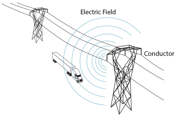
As illustrated, an individual may make contact with a capacitively energized truck, providing a path to ground through their hand and body. Depending on the magnitude of capacitive coupling, this current is perceptible and possibly hazardous.
Human Electrical Susceptibility
Human’s electrical susceptibility is dependent on current magnitude, electrical frequency, and duration. The 60 Hz frequency that power operates in North America may be particularly hazardous at relatively minimal values. Various studies have provided a range of experiences relative to the shock received and is summarized in the table below.
| Current | Human Experience |
|---|---|
| 1 mA | Perception |
| 1 – 6 mA | Unpleasant but able to release energized object |
| 6 – 15 mA | Painful but may be able to release energized object |
| 15 – 23 mA | Painful and impossible to release energized object |
| 50 – 200 mA | Fibrillation possible |
This table illustrated that relatively minimal current was sufficient to cause immediate harm to individuals, as well as that the thresholds could significantly vary from person to person. For some individuals, a current of 6 mA or greater is sufficient to cause involuntary muscle contraction. If a person were to contact an object that has sufficient voltage to drive this current, it may be impossible for them to let go without assistance.
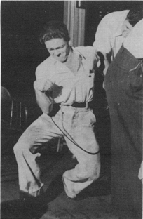 This photo illustrates this involuntary muscle contraction with obvious signs of pain on the volunteer’s face as they hold an energized conductor.
It should be noted that there is more research into long term sequelae effects of electric shock. Much of the engineering studies are based on high impact events that are instantly hazardous or fatal.
5 mA Calculation
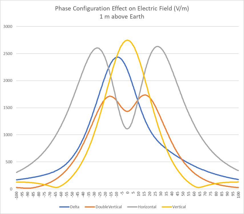
High voltage transmission lines over roadways, parking areas, and fields may require calculations to verify the “let-go” current threshold is not exceeded. NESC uses a 5 mA current as the threshold for “let-go” current as this was deemed conservative from the research available. As this effect is driven by the electric field, it is important to understand the effect phase configuration has on the electric field and generally maximum field strengths across the right-of-way. The figure below provides the electric field strength of multiple phase configurations with identical voltage levels and phase spacing.
While hand calculations are possible, there are several variables that are challenging to consider in simple hand calculations. For example, calculating the change in electric fields based on separation from the phases in multiple axes and incorporating the phase’s bundle and sag characteristic effect. These changes in fields should be considered over the pertinent surface area of the recipient object. For this reason, EMF analysis software like XGSLab are used to model the transmission line and pertinent recipient objects.
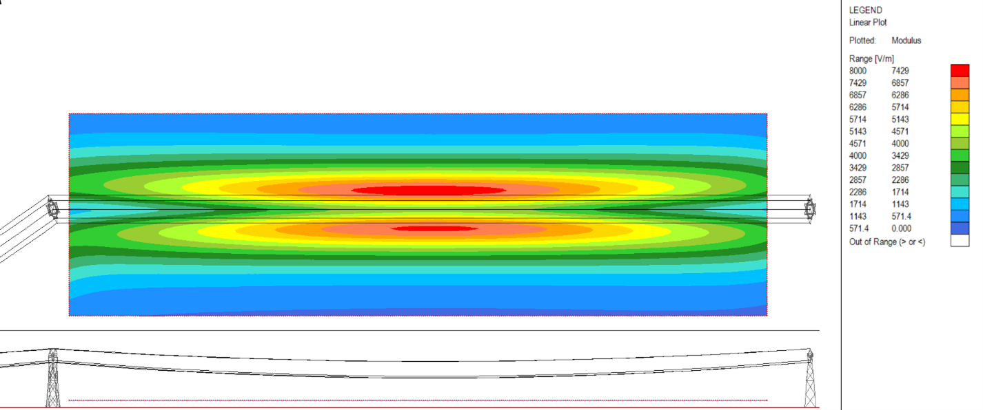
The XGSLab output above shows the electric field strength at various locations along the right-of-way for a horizontal high voltage line, in which it may be challenging to average the changing field in the area pertinent to the recipient object.
As with most studies, the first stage is data acquisition. Typical data required of the transmission line includes:
- Voltages level, including the highest permitted voltages
- Plan and profile indicating minimum clearance and attachment elevations
- Phasing configuration
- Outage scenarios applicable to lines with multiple circuits
The next stage of the analysis is determination of the recipient object. Cars and semitrucks are the primary recipient of concern for roadways and parking areas. Maximum dimension of these vehicles can be determined based on the limits set by entities like the Department of Transportation, other regional restriction authority, or simply property restrictions. Where lines pass over farmland, combines would be applicable recipients for analysis. An engineer evaluating the transmission line’s electric field effects in publicly accessible locations may need to consider other metallic objects, including isolated fencing or a metallic roof where wood supports isolate the metallic structure.
Modeling and Analysis Scenarios
Generally, a wireframe mesh of the recipient object is sufficient for calculating the coupled voltages. Below illustrates a model of a transmission line above a semitruck approximated with a wire mesh in XGSLab.
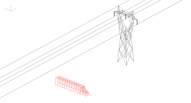
The truck is elevated from the earth, and only one transverse impedance is added (often 1,000 Ω) to represent a person that may contact the capacitively energize tractor and trailer. The calculated results provide the current that would develop if an individual were to contact the vehicle.
It is important to accurately place phase conductor’s elevation as their proximity significantly affects the analysis results. Similarly, vehicles may have multiple configurations and locations to consider. Below is a simple example of various locations of the semitruck and corresponding capacitively coupled current.
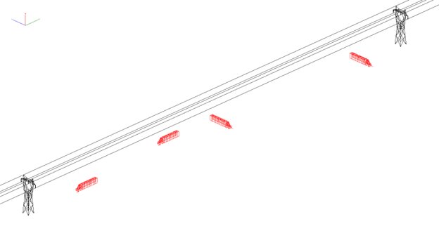
As expected, the resulting current from a person contacting the truck shows great variability, shown in the table below.
| Recipient Semitruck Location | Contact Current (mA) |
|---|---|
| 1. Parallel truck below phases and near tower | 0.3 |
| 2. Parallel truck near ROW and midspan | 4.8 |
| 3. Perpendicular truck near ROW and midspan | 1.1 |
| 4. Perpendicular truck below phases near tower | 0.2 |
Typical cases to consider with the recipient objects include vehicles in parallel and perpendicular orientation to the transmission line. The parallel vehicle often maximizes the exposure area, providing the worst-case results. With that said, phasing arrangements, accessibility of recipient objects, and some vehicle design may see greater voltages when in a perpendicular arrangement. For finding the worst-case recipient locations, plotting the electric field, as was shown previously in this article, highlights the areas where maximum fields are found.
The analysis scenarios can vary, but for single circuit transmission lines, often the maximum operating voltage is the only condition to consider. For multi-circuit lines, additional phases can present unique fields at ground level based on full operation or partial outages. An engineer must consider applicable operating conditions and apply these scenarios to the study.
Mitigation Approaches for NESC 5 mA Studies
Where analysis determines the NESC 5 mA rule is exceeded, mitigation is required. Mitigation can be a combination of approaches, including:
- Elevating the phase conductor
- Optimizing the phasing configuration
- Shielding areas of concern
- Grounding recipient objects
In some scenarios, particularly for buildings or stationary structures, it may be possible to ground and bond the recipient metallic object. This dissipates the capacitive charge on the recipient, significantly reducing the shock hazard. This approach is not feasible for vehicles; thus, a shielded approach may be necessary. A shield/ground wire may be placed below the phase conductors of the line to reduce electric field strengths on the earth surface. This can also provide improved lightning performance, and thus improve reliability. Grounded metallic barriers can also shield vehicles to prevent hazardous coupling to public and personnel vehicles.
Elevating the phase conductor is one of the most common approaches to mitigating the electrostatic shock hazards. The additional ground clearance is commonly achieved by increasing tower heights and reducing sag to reduce electric field strengths. Additional tower height may not be feasible so engineers may consider optimized phasing approaches.
In multi-circuit lines, phasing can be arranged such that maximum cancellation of the electric field is achieved. As illustrated previously in this article, delta phasing configuration can help to reduce the electric field magnitudes from single circuit transmission lines while maintaining the same phase to phase separation.
When concerned that the NESC 5 mA rule is exceeded, it is relatively simple to calculate the effects of the transmission line’s electric field to verify electrostatic effects do no exceed hazardous values with the powerful XGSLab software. XGSLab allows engineers to explore several mitigation options to help determine efficient means to assure safety for the public and personnel in the vicinity of high voltage transmission lines while meeting the NESC 5 mA codes.