Grounding Analysis
Electrical grounding is a broad field, but with regard to the power industry a grounding (earthing) system analysis refers to a specific subject. To gain an understanding of a grounding system analysis, we should start by answering: What is a grounding system?
Free Intro to Grounding Analysis Book
 Learn more about the concepts in this article and related content in the Introduction to Grounding Analysis Book download for free! This free book serves those in the power industry responsible for analyzing the performance of a grounding (earthing) system, specifically with regard to IEEE Std 80, Guide for Safety in AC Substation Grounding. It is a comprehensive and valuable resource that shows the need for and how to do grounding analysis.

Grounding System
A grounding system is a network of ground electrodes, which are simply conductors imbedded into the earth. Grounding systems are an important part of the power infrastructure and are found at substations, switchyards, generation sites, and industrial facilities. As an example, at a substation, bare copper is directly buried into the earth typically as a grid or mesh, as shown in the image below:
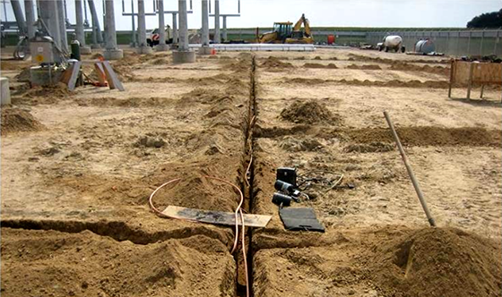
Grounding electrodes are typically horizontally placed bare copper conductor buried 18 – 24 inches below grade with vertically installed ground rods. Some areas require one or multiple ground wells to achieve the grounding system design objectives.
Grounding systems are designed and assessed to improve electrical safety and operation. The primary purposes of a grounding system include:
- Helping to ensure personnel and public safety.
- Facilitating proper equipment operation under normal and faulted conditions (some protection schemes require sufficient ground current to detect and operate for a fault).
- Preventing or reducing equipment damage or fault escalation from a power system fault.
- Preventing or reducing equipment damage from lightning effects.
When to Perform a Grounding System Study
When a new power system is installed a grounding system study must be performed. With existing power systems, it may be more challenging to determine when a grounding system study is needed. The list below provides some scenarios that would require a new grounding study be performed:
- Maintenance and field measurements uncover deficiencies
- Visual inspection may indicate missing or corroded connections.
- Grid impedance testing results in grounding system resistance exceeding design value.
- Elevated point to point measurements indicating discontinuity or weak grounding and bonding.
- Changes to system protection
- Increasing the duration of ground fault current.
- Changes to short circuit duty
- Replacement circuit breakers for short circuit duty purposes.
- Replacing or adding of transmission lines.
- Addition or replacement of transformer.
- Arrangement modifications for equipment and fence
- Altering the size of the grounding system can increase the system impedance.
- Moving the fence can create hazards that are accessible to the public.
- Removing equipment may result in damage to conductors
- Missing design drawings or study documentation
- A new grounding analysis is likely necessary to have engineered design to reduce hazards.
Grounding Study
A grounding system analysis or study is the evaluation of the grounding system in meeting its design objectives. In the power industry, the primary focus is addressing the aspect of personnel and public safety. IEEE Std 80 provides guidance for safety related to grounding in AC substations. This standard highlights the dangerous conditions that may occur during a ground fault that can severely or fatally injure individuals in the area or in contact with metallic objects.
During a ground fault, current flows into or out of a grounding system and the electrical potential of the grounding system and surrounding soil are elevated relative to remote earth. This is referred to as the ground (earth) potential rise, and is illustrated in the image below:
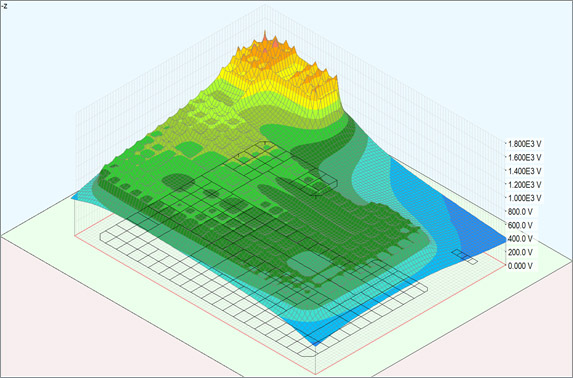
Bonding and grounding equipment at a site elevates all metallic objects to the ground potential rise. Knowing that current will travel in all available paths, sufficient voltage gradients may be present on the earth’s surface to produce catastrophic current to flow through personnel or public within the affected area. A lower grounding system impedance results in a lower ground potential rise, but designing to a specific impedance, such as 5 ohms or less, is not a measure of an effective grounding system for personnel safety. Determining the touch and step voltages that may occur at a grounding system, compared to the permissible limits, is the correct measure of a grounding system efficacy. Generally, three variables drive the grounding system performance:
- Grounding system physical design and geometry
- Soil electrical characteristics
- Ground fault current magnitude and duration
It is important to note that each component is complex, often varying over time, and significantly affects the conclusions of a grounding analysis. Engineers performing a grounding system study must consider the accuracy of the data and how changes in theses variables can affect a study’s conclusion. In addition, the design must verify all equipment is bonded, size the equipment and below grade ground conductors, and possibly evaluate effects on adjacent facilities.
Hand calculations are available for determining a grounding system performance; however, critical assumptions are made that often result in over design or under design of the grounding system. Fortunately, software such as XGSLab, enables engineers to more accurately evaluate these complex variables efficiently improving safety.
Related Topics Q&A
Q - What is remote earth?
A - This a point of earth that has no electric potential and is not affected by the ground potential rise of the grounding system under analysis.
Q - Why add crushed rock surfacing?
A - Crushed rock surfacing typically helps by adding a high resistivity material below an individual’s feet, reducing current flow during a fault. Not all rock is the same and testing should be performed to verify resistivity.
Q - Grounding Design Margin?
A - Grounding systems are designs should consider how components, like fault current availability, may increase over the 30 or more year lifespan of the system as a part of a growth margin. Similarly, a safety margin may be appropriate to make a grounding system more robust from inaccuracy that occur in soil resistivity measurements, installation, or other components.
Q - Grounding vs Bonding?
A - Bonding is simply a connection of two or more metallic objects with a low impedance connection. Grounding indicates the metallic objects is connected to the grounding system with a low impedance connection
Q - Are soil resistivity measurements necessary?
A - Soil resistivity is a major factor in the grounding system performance. It drives the system impedance, ground potential rise, and touch/step voltages. Soil resistivity measurements are simple to perform and equipment may rented several companies rent. Poor data results in a poor design, and wasted material if it doesn’t serve the engineering purpose.
XGSLab™ Grounding Solution
XGSLab is one of the most powerful software for electromagnetic simulation for power, grounding and lightning protection systems and the only software on the market that takes into account International (IEC/TS 60479-1:2005), European (EN 50522:2010) and American (IEEE Std 80-2000 and IEEE Std 80-2013) Standards in grounding system analysis.