Grounding Analysis – Ground Fault Current
A ground fault at a power system could produce hazardous touch and step shock hazards. Recognizing the multiple aspects that are incorporated into the fault current data for a grounding study is essential to accurately evaluate a substation or other facility’s grounding system to reduce these hazards. This article discusses the components of power system fault data as they are applied for grounding system studies. In addition to fault data, other factors are discussed in the grounding analysis article.
Free Intro to Grounding Analysis Book
 Learn more about the concepts in this article and related content in the Introduction to Grounding Analysis Book download for free! This free book serves those in the power industry responsible for analyzing the performance of a grounding (earthing) system, specifically with regard to IEEE Std 80, Guide for Safety in AC Substation Grounding. It is a comprehensive and valuable resource that shows the need for and how to do grounding analysis.

Ground Fault Scenario
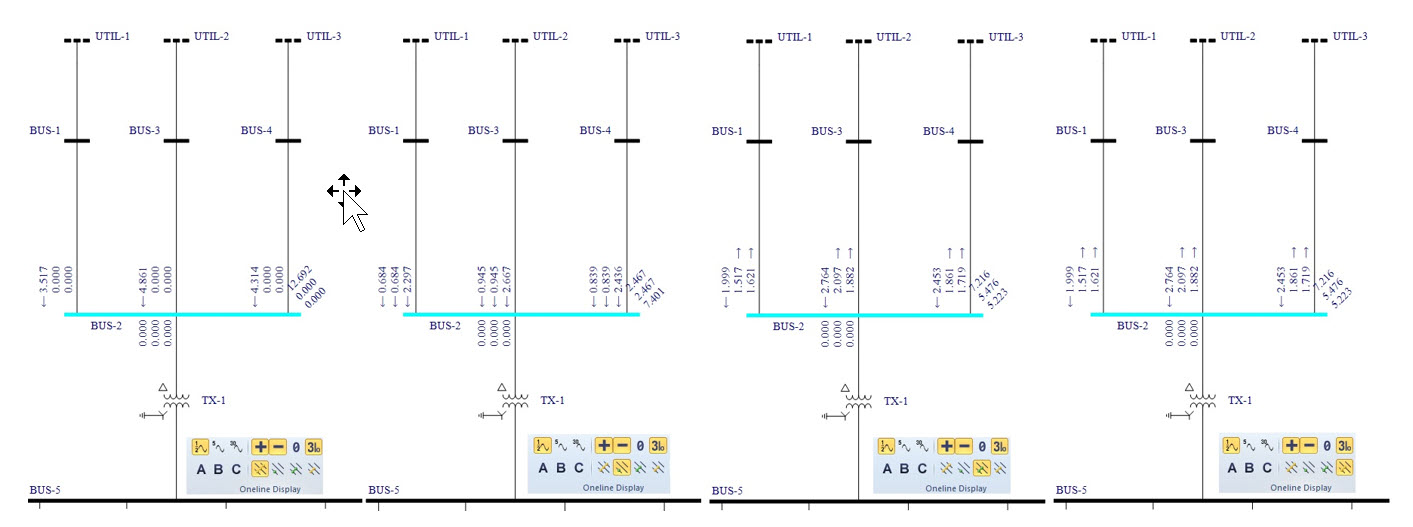
As a condition of a grounding system study, a fault scenario is assumed to occur that provides ground current through the system under investigation, energizing the bonded and grounded components. Referencing symmetrical components concepts, this ground current exists for specific fault types with a zero-sequence component. The zero-sequence component of the fault can pass through the grounding system and through the earth path. Several fault types, shown in EasyPower below, highlight that the zero sequence component is present for the single-line-to-ground (SLG) and double-line-to-ground (DLG) faults:
An illustration below shows an SLG fault at a central substation, where a bonded and grounded structure at the site contacts a phase conductor. The portion of the fault current that flows through the grid will correspond to a ground potential rise (GPR) and this voltage could result in hazardous touch and step shock hazards. As expected, the faulted site experiences a GPR due the impedance of the grounding system and the fault current returning to its remote source.
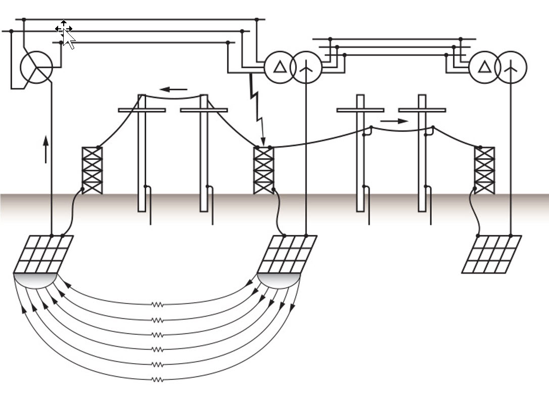
The current has multiple paths to return to the source, which is commonly referred to as the fault current split and is discussed in more detail later in this article. During the fault, a GPR is simultaneously present at the source site and could produce hazardous touch and step voltages as well as at the central site. Evaluating a site, it is important to note that a site’s GPR may develop from a fault with a zero sequence component onsite or at a remote location. Engineers should consider multiple fault scenarios to determine the worst-case conditions for evaluating the grounding system performance.
Ground Fault Current Data
There are three primary aspects of fault data that contribute to the grounding system evaluation:
- Fault current magnitude
- Fault duration
- Fault X/R ratio
Each fault scenario may have unique factors that influence the fault data as it is incorporated into a grounding study.
Fault Current Magnitude
The fault current magnitude is dependent on the power system interconnection and voltage levels associated with the fault scenario. Grounding studies can consider faults at various voltage levels of the site under analysis to determine the maximum ground current. The maximum ground current will produce the largest GPR, which may be the worst-case scenario for evaluating touch and step voltages. The largest touch and step voltages from the maximum ground fault current may not be the worst-case condition, as the duration of the fault affects the applicable voltage limits.
Fault Duration
The duration of a fault is determined by the operation of protective and interrupting devices in the power system. Typical protection schemes include multiple devices and sensing elements to provide fast selective primary protective fault clearing with slower backup protection.
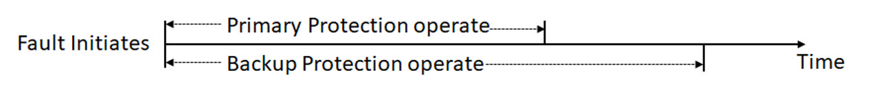
Guidance from IEEE Std 80 finds both primary and backup fault clearing times are acceptable to use for evaluating a grounding system performance, noting that backup clearing times will yield a more conservative result. Historical review of protective relay operation for fault events is recommended to determine the best engineering decision for a utility or facility.
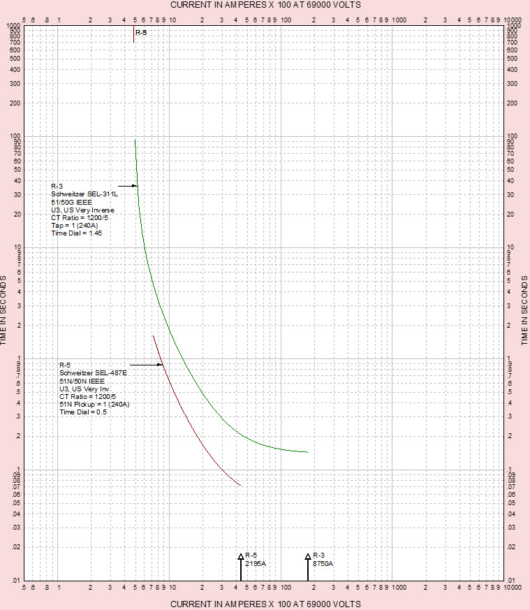
Protective elements for ground fault detection benefit in that they may be set more sensitively and operate more rapidly when compared to phase overcurrent protection. The TCC chart below shows primary and backup ground overcurrent curves that are coordinated for optimal sensitivity and security.
Fault X/R Ratio
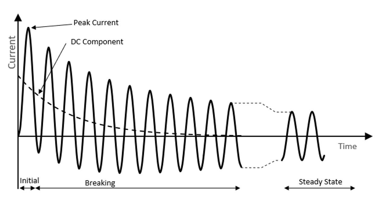
A power system’s inductive and resistive impedances may significantly affect the fault current characteristics. Power systems with greater X/R ratio produce a greater DC offset in the event of a fault. A classic visual representation of the DC offset on an AC curve is shown below.
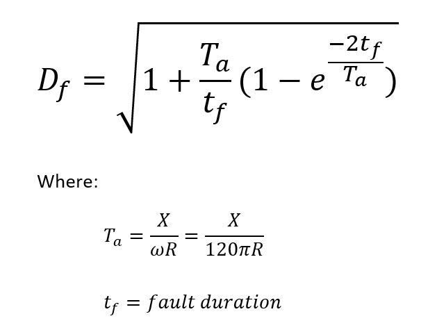
The DC offset may increase the peak current considerably and increases the cumulative fault current through various paths. Regarding a grounding analysis for personnel safety, the cumulative current through the human body could result in fatal touch and step shock hazards and should consider this DC offset’s effect. IEEE Std 80 provides a calculation method for considering the cumulative effect of the X/R ratio, described as the decrement factor (Df) and shown below.
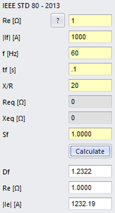
The decrement factor incorporates the X/R ratio, the frequency, and duration of the fault. Essentially this X/R decrement factor is a method to equate the DC offset as an average fault current, thus resulting in greater touch and step voltage hazards. This decrement factor can be implemented through hand calculations or with tools like XGSLab. A screenshot example of the decrement factor calculation shows Df equals 1.23 for a fault cleared in 0.1 seconds with an X/R that is equal to 20.
Fault Current Split
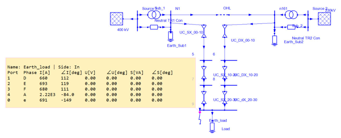
For many ground fault events, a portion of the current will take alternative paths that do contribute to a GPR at the grounding system under analysis. Determining the fault current split provides the percentage of fault current that goes through the grid producing a GPR and the portion that takes alternative paths reducing the maximum GPR. Considering the fault current split allows for a more accurate analysis and more efficient grounding system design. Alternative paths often include a transmission line’s overhead wires, distribution neutral wires, and cable shielding and armor. There are several methods for calculating the fault current split, but a common simplified approach is to calculate the equivalent impedance of the alternative paths and enter those Req and Xeq values into the XGSLab split factor tool. Another simplified approach is provided in the IEEE Std 80 Annex C graphical curves, where an engineer can quickly approximate the fault current split with the number of transmission and distribution lines connected to the grid under analysis. More thorough investigation is performed by software, such as NETS, that use the phase component method, which can model a complicated meshed power system such as the two stations with an interconnected transmission line and cables feeding a central site. The NETS model below shows that of the 2.22 kA phase A fault, only 691 A will produce a GPR (through e) with the remaining taking the cable shields paths (D,E,F).
Simplified approaches, especially referencing Annex C of IEEE, require engineering judgement to determine if the assumptions included in the methods are applicable to the grounding system under investigation.
With many engineering studies, the quality of data inputs dramatically affects the quality of the output. Understanding the multiple aspects of the fault current data for a grounding system analysis can guide more accurate and efficient designs to reduce personnel and public shock hazards.
Some Related Topics Q&A
Q - What is remote earth?
A - This a point of earth that has no electric potential and is not affected by the ground potential rise of the grounding system under analysis. For a fault source, it must be remote earth away from the fault to allow full ground potential rise, otherwise there is an overlapping zone of influence and/or direct metallic conduction to reduce/eliminate GPR.
Q - What is protection sensitivity?
A - Sensitivity refers to the ability of the protective device to “see” a fault condition.
XGSLab™ Grounding Solution
XGSLab is one of the most powerful software for electromagnetic simulation for power, grounding and lightning protection systems and the only software on the market that takes into account International (IEC/TS 60479-1:2005), European (EN 50522:2010) and American (IEEE Std 80-2000 and IEEE Std 80-2013) Standards in grounding system analysis.