Types of Studies With XGSLab Software
Grounding Study
Summary
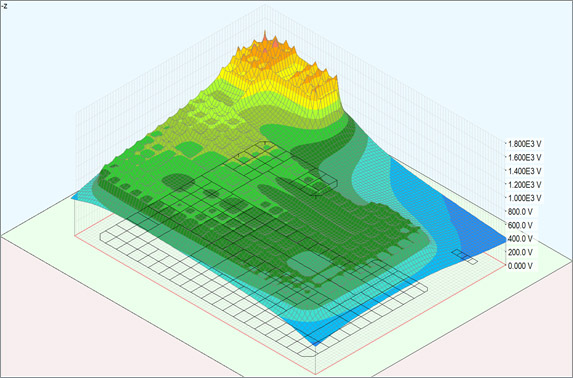
A grounding study is the study of a metallic system (grounding electrodes) in the earth. Typical applications of this study are at substations, switchyards, generation sites, communication sites, and industrial facilities. IEEE 80 is the Guide for Safety in AC Substation Grounding related to this study.
Why Is This Needed?
- For personnel and public safety.
- To facilitate proper equipment operation under normal and faulted conditions.
- To prevent or reduce equipment damage or fault escalation.
- To prevent or reduce equipment damage from lightning effects.
How To Do a Grounding Study
- Evaluate soil resistivity measurements to approximate the electrical characteristics of the soil.
- Determine the permissible touch or step voltage limits per the applicable standard (such as IEEE Std 80).
- Develop a system model and calculate the grounding system impedance.
- Assess the portion of the available fault current that will return to its source going through the grounding system to earth compared to the portion that takes alternative paths.
- Determine the worst-case ground potential rise, touch voltage, and step voltage. If any criteria are exceeded, redesign the grounding system and repeat the process.
- Create documentation for future engineering work and review.
Related Terms
- Ground Potential Rise (GPR) - This is the electrical potential that a ground grid and the surrounding soil may attain. Ground potential rise may also be described as the Earth Potential Rise.
- V(GPR)=I(Ground_Current) R(Grid_Resistance)
- Touch and Step Voltages - Voltages that an individual may be subjected to during a ground fault
Additional Grounding Study Resources:
- Full Article - Grounding Analysis
- Webinar Video - An Introduction to Grounding
- Industry Standard - IEEE Std 80 Guide for Safety in AC Substation Grounding
Free Intro to Grounding Analysis Book
 Learn more about the concepts in this article and related content in the free download of the Introduction to Grounding Analysis Book! This free book serves those in the power industry responsible for analyzing the performance of a grounding (earthing) system, specifically with regard to IEEE Std 80, Guide for Safety in AC Substation Grounding. It is a comprehensive and valuable resource that shows the need for doing a grounding analysis and how to perform it.

Transferred Voltage Study
Summary
A transferred voltage study is similar to a grounding system analysis; however, the focus of the study is to evaluate the conductive effects of the ground potential rise at adjacent structures, equipment, or utilities. The grounding system effects must be known to evaluate the effects on nearby recipients. Typical applications of this study are at substations, switchyards, generation sites, and industrial facilities.
Why Is This Needed?
- For personnel and public safety.
- To facilitate proper equipment operation under faulted conditions.
- To prevent or reduce equipment damage.
How To Do a Transferred Voltage Study
- Evaluate soil resistivity measurements to approximate the electrical characteristics of the soil.
- Determine agreeable touch/step voltage limits with the affected parties (often applying the IEEE Std 80).
- Calculate grounding system impedance.
- Assess the portion of the available fault current that will return to its source going through the grounding system to earth compared to the portion that takes alternative paths. Note that the recipient may be considered an alternative path for the current and must be accurately assessed.
- Determine the worst case ground potential rise, touch voltage, and step voltage at and near the recipient object. If any criteria are exceeded, mitigation may be applied to the grounding system or recipient.
- Create documentation for future engineering work and review.
Additional Transferred Voltage Study Resources
- Full Article - Transferred Voltage Hazards
- Webinar Video - Evaluating & Mitigating Transferred Voltage Hazards
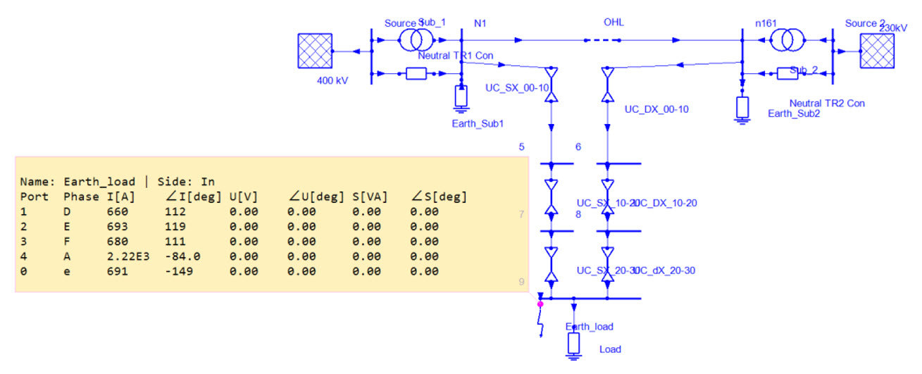
Ground Fault Split Factor Calculation
Summary
A ground fault split factor calculation is typically done in support of a grounding system analysis; however, the focus of this calculation is to determine the total ground fault current that will produce a ground potential rise at a grounding system. Ground fault events at substations, switchyards, and generation facilities commonly have connections to transmission shield wires and neutral conductors that provide an alternative path for a portion of the total ground fault current, thereby reducing local touch and step voltages. The IEEE 80 substation grounding standard provides estimated fault split current calculations with several limiting assumptions. A detailed ground fault split calculation determines a 2 kA fault results in approximately 690 A through the earth.
Why Is This Needed?
- Grounding system costs may be reduced by calculating the fault current split that lower ground potential rise, reducing touch and step voltage hazards.
How To Do a Ground Fault Split Factor Calculation
- Determine the total number of paths for ground current, including each transmission line with shield wires, each distribution line with neutrals, and cables with buried/concentric neutrals.
- Model each path’s impedance considering phase configurations, conductor’s material, line length, structure ground resistance, and fault sources (for mutual coupling).
- Calculate the approximate grounding system impedance as impedance for a fault.
- Determine the portion of the available fault current that will return to its source through the grounding system compared to the alternative paths.
- Create documentation for use in efficient grounding analysis, future engineering work, and engineering review.
Additional Ground Fault Split Factor Calculation Resources
- Full Article - Ground Fault Current
- Industry Standard - IEEE Std 80 Guide for Safety in AC Substation Grounding
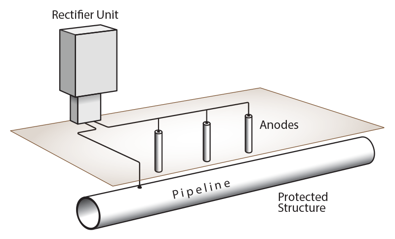
Cathodic Protection Study
Summary
Buried and submerged metals corrode as a part of an electrochemical reaction. One method to reduce this corrosion is to provide active cathodic protection, in which a DC voltage is applied upon an anode and the cathodically protected structure.
Why Is This Needed?
- It increases the lifespan of buried or submerged metals.
- It provides adjustable levels of protection.
- It provides monitoring of the protected system corrosion.
How To Do a Cathodic Protection Study
- Acquire data for the system to be protected, such as material, layout/routing, and coating material.
- Acquire data of the field measurements in existing sites and soil resistivity measurements.
- Develop a model of the protected system with ICCP system design including sources and anodes.
- Adjust the location, voltage, or design of the ICCP system to meet the target voltage on the protected system.
- Create documentation for future engineering work and review.
Additional Cathodic Protection Resources
- Full Article - Cathodic Protection
- Industry Standard - AMPP Cathodic Protection Standards
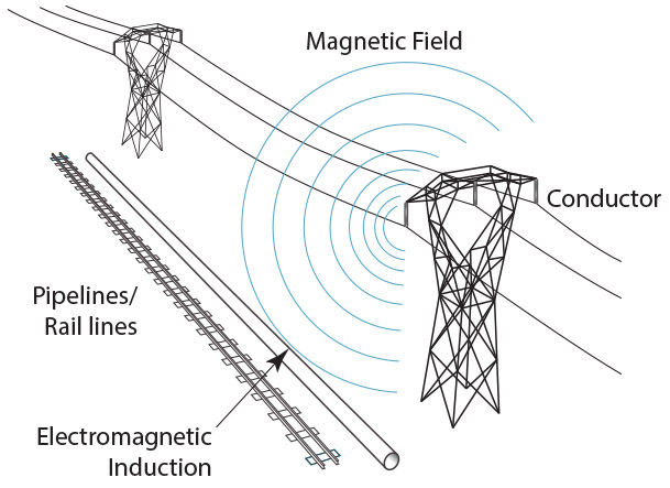
AC Interference Study
Summary
This is the evaluation of the AC transmission lines collocated or adjacent to other metallic objects. Typical recipients are other utilities such as pipelines or railroads. Transmission lines crossing or parallel to other linear utilities can have voltages induced, capacitively coupled, or even conducted from the transmission line to the recipients. IEEE 2746 Guide for Evaluating AC Interference provides guidance on multiple recipients while NACE SP0177 provides guidance on AC interference/AC Corrosion for pipelines.
Why Is This Needed?
- To protect personnel and the public during normal and faulted conditions.
- Touch voltages and step voltages may occur near the recipient.
- The transmission line steady state condition may affect the equipment operation.
- AC corrosion can accelerate the normal pipeline corrosion and reduce the cathodic protection system effect.
- Railroad track equipment may operate incorrectly as signaling interference occurs.
- The transmission line faulted condition may damage pipelines or railroad equipment.
- Lightning protection systems, supporting equipment, and coating materials may all be damaged from power system faults.
How To Do an AC Interference Study
- Determine agreeable criteria with the affected parties based on available guides.
- Acquire data for the transmission line, such as plan and profile, phasing, electrical loading, and fault current availability.
- Acquire data for the recipient such as alignment drawings, appurtenance locations, equipment types, and other applicable concerns.
- Acquire data of the field measurements in existing sites and soil resistivity measurements.
- Develop a model of the collocated transmission line and recipient to calculate inductive, capacitive, and conductive effects. Most AC interference studies are too complex to perform hand calculations.
- Mitigate for any criteria that are exceeded that may be applied to the transmission line or recipient (pipeline/railroad).
- Create documentation for future engineering work and review.
Additional AC Interference Resources
- Full Article - AC Interference in Shared Corridors
- Webinar Video - AC Interference in Shared Corridors
- Industry Standard - IEEE Std 2746 Guide for Evaluating AC Interference on Linear Facilities Co-Located Near Transmission Lines
- Industry Standard - AMPP NACE SP0177 Mitigation of Alternating Current and Lightning Effects on Metallic Structures and Corrosion Control Systems
NESC 5 mA Rule and Calculation
Summary
A transmission line’s electric field may capacitively couple with nearby objects. When standard transmission line heights are not feasible or create additional risks that make coupling hazardous, an analysis may be performed to calculate the voltage on objects and buildings. The National Electric Safety Code (NESC) 5 mA Rule provides additional guidance on this calculation.
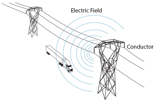
Why Is This Needed?
- An electric field (capacitive coupling) may occur on semitrucks, combines, storage buildings/tanks, metal roofed buildings, etc., to cause 5 mA (the “letgo” threshold) to flow when an individual touches the metal object.
How To Do a 5 mA Calculation
- Acquire data for the transmission line—primarily conductor elevation and voltage level.
- Develop a model of the collocated transmission line and recipient object.
- Determine if personnel or public contact with the object and soil could cause 5 mA to flow. Mitigate if needed.
- Create documentation for future engineering work and review.
Additional NESC 5 mA Calculation Resources
- Full Article - Understanding NESC 5 mA Let-Go Shock Hazard
- Industry Standard - IEEE NESC Book
Lightning Shielding Analysis
Summary
Regions where lightning events may damage or destroy buildings, facilities, power systems, and other infrastructure require lightning protection systems. NFPA 780, IEEE 988, and several other standards provide guidance on lightning protection systems design. A lightning shielding analysis determines if a design intercepts damaging lightning strikes.
Why Is This Needed?
Lightning shielding analysis determines if a lightning protection system is insufficient, overdesigned, or adequately shielding a facility, electrical power system, or other infrastructure from a direct lightning strike. Gaps in a lightning protection system design lead to greater risk of hazardous lightning damage.
How To Do a Lightning Shielding Analysis
- Acquire data for the victim structure’s geometry.
- For power systems, determine the Basic Lightning Impulse Level (BIL) or Critical Flashover Voltage (CFO) for each voltage level.
- Determine the lightning striking distance, driving the Rolling Sphere Method’s sphere diameter.
- Develop a model victim structure with an initial lightning protection system shielding design.
- Determine if the structure and equipment is shielded from a direct strike or mitigate if needed.
- Create documentation for future engineering work and review.
Additional Lightning Shielding Analysis Resources
- Full Article - Lightning Protection Systems
- Webinar Video - Save Time With Rolling Sphere Lightning Protection Design
- Industry Standard - NFPA 780 Standard for Installation of Lightning Protection Systems
- Industry Standard - IEEE Std 998 Guide for Direct Lightning Stroke Shielding of Substations
- Industry Standard - IEC 62305 Protection Against Lightning
Lightning Transient Analysis
Summary
Regions where lightning events may damage or destroy buildings, facilities, power systems, and other infrastructure require lightning protection systems that are adequately sized to dissipate the lightning’s energy. The lightning protection system may rely on properly sized downleads, grounding systems, and may dissipate energy through surge protective devices. Additionally, lightning protection designs may rely on insulating components to withstand the impulse voltages that may see greater lightning impulse due to poor grounding, such as a backflash event on a transmission tower.
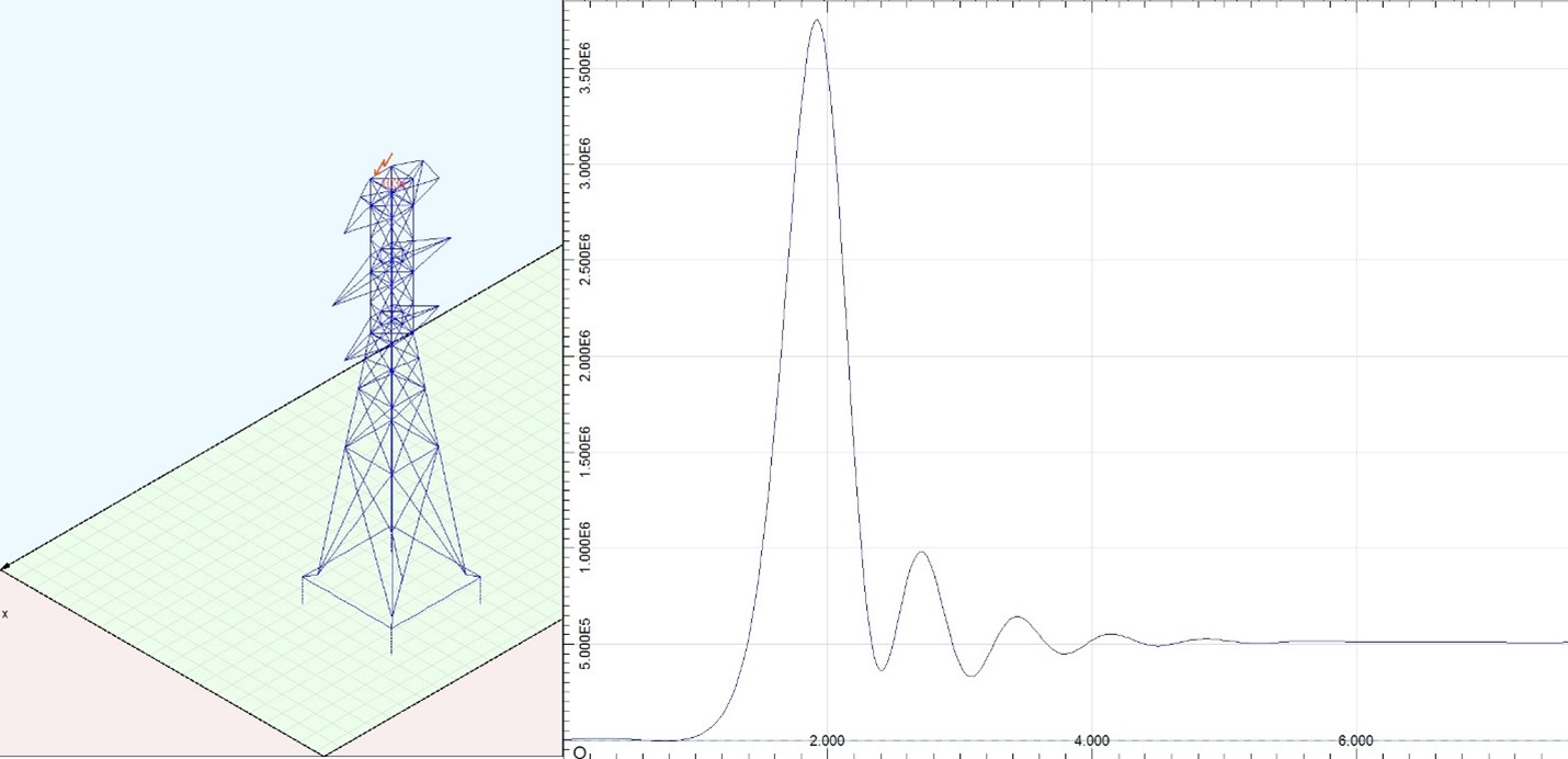
Why Is This Needed?
- Lightning transient analysis evaluates all lightning protections components to verify lightning energy can be safely carried without fusing downleads.
- Verifies surge protection devices thresholds are met to operate and device ratings are not exceeded.
- Evaluates whether peak lightning impulse voltage exceeds voltage withstands for critical points of the lightning protection system.
How To Do a Lightning Transient Analysis
- Acquire data for the lightning protection system design and critical components specifications for operating thresholds and maximum ratings.
- Develop a model with the lightning protection system design, and tag surge protection equipment and critical locations for flashover concerns.
- Determine maximum lightning stroke current, which is typically derived as part of the shielding analysis, and energize the model with the lightning impulse.
- Evaluate whether downlead, surge protective devices, and withstand voltages are within tolerable values.
- Create documentation for future engineering work and review.
Additional Lightning Transient Analysis Resources
- Full Article - Lightning Protection Systems
- Webinar Video - Bonded vs Isolated Lightning Protection Concepts & Their Application to Explosive Areas
- Industry Standard - IEC 62305 Protection Against Lightning
XGSLab™ Grounding Solution
XGSLab is one of the most powerful software for electromagnetic simulation for power, grounding and lightning protection systems and the only software on the market that takes into account International (IEC/TS 60479-1:2005), European (EN 50522:2010) and American (IEEE Std 80-2000 and IEEE Std 80-2013) Standards in grounding system analysis.